
Mechanical Inspection
Inspection of structures, lifting systems, wheels, rails, fasteners, wear and deformation.
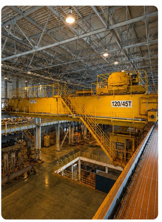
Technical & engineering expertise — LGEN supports you through a complete evaluation of your overhead cranes with a full diagnostic and rigorous 3D geometric inspection, to ensure the safety, reliability and performance of your equipment.
The geometry of runway systems directly influences the mechanical behavior of an overhead crane and the service life of its components. Any deviation from regulatory tolerances can cause abnormal wear on wheel flanges, premature component wear, excessive lateral forces, vibration and operational risks.
A comprehensive approach: general diagnostic + 3D geometric inspection. Our service is not limited to geometric inspection — we carry out a full general diagnostic.
Inspection of structures, lifting systems, wheels, rails, fasteners, wear and deformation.
Inspection of control cabinets, wiring, power supplies, protections, control and safety devices.
Static load tests according to current standards to verify the strength of load-bearing elements.
Dynamic load tests to validate in-service behavior and the stability of the overhead crane.
Compliant with current standards: ISO 12488-1, 4301-1, FEM 1.001, ISO 9927, EN 15011 and other applicable standards.
Deviations in rail alignment, level, parallelism or straightness.
Forced guidance of follower wheels causing accelerated wear.
Wear on wheel flanges, wheels and rails, increased clearances and vibration.
Degraded operation, discomfort, structural risks and material fatigue.
Unplanned downtime, reduced equipment service life, compromised safety.
Our services are delivered by an experienced multidisciplinary team including:
All interventions are carried out or supervised by our subject-matter expert engineers, ensuring the quality, reliability and compliance of our analyses.
Reference standards: ISO 12488-1:2012 (Class 2) and ISO 8306:2017
| No. | Inspected Parameter | Tolerance per ISO 12488-1:2012 (Class 2) | Tolerance per ISO 8306:2017 |
|---|---|---|---|
| 1 | Track gauge deviation (rail span) s = distance between inner rail faces | ± [ 3 + 0.25 × (S − 10) ] (max. ± 15 mm) | ± [ 3 + 0.25 × (S − 10) ] (max. ± 15 mm) |
| 2 | Level difference between the two rail rows (ΔH) | ≤ 10 mm | ≤ 10 mm |
| 3 | Horizontal deviation (parallelism) between the two rails (P) P = horizontal deviation over the full length | ± [ 3 + 0.25 × (L − 10) ] (max. ± 15 mm) | ± [ 3 + 0.25 × (L − 10) ] (max. ± 15 mm) |
| 4 | Rail vertical straightness f = maximum deviation from a straight line | 2 mm / 2 m | 2 mm / 2 m |
| 5 | Rail local horizontal straightness | 1 mm / 2 m | 1 mm / 2 m |
| 6 | Rail total horizontal straightness | ± 10 mm | ± 10 mm |
| 7 | Rail joint gap | 2 to 3 mm | 2 to 3 mm |
| 8 | Rail joint vertical offset | ≤ 1 mm | ≤ 1 mm |
The tolerances indicated apply under normal operating conditions and for structures that are properly installed and maintained.
Quality, rigor and transparency at every stage of our service for reliable, high-performance overhead cranes that meet applicable standards.
"LGEN, your technical partner for durable and effective solutions."
Our engineers support you from the 3D geometric survey through to the corrective action plan, anywhere in Morocco.